


Processing
Planing and profiling MDF edges
One of the main advantages of MDF over other wood based sheet materials is the ease of shaping panels and moulding edges ready for finishing to a high appearance standard with minimum sanding and filling. Almost any profile can be cut in MDF for applications in the furniture, fitment and building industries.
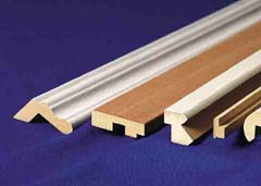
Simple profiles with curved edges are preferred because they can be sanded easily in preparation for finishing and, in heavy duty situations, have greater resistance to impact damage. Regardless of the complexity of the profiles, all sharp (ariss) edges should be slightly rounded to ensure good coverage of paint or lacquer and to increase the resistance of the finish to impact damage.
Carbide cutters
The softer K10 to K20 grades of carbide are used for brazed on inserts as the similarity of the coefficients of thermal expansion of these tool grades and the tool body material reduces the risk of cracking.
The introduction of disposable tips allows the harder K1 to K5 grades to be used with the advantages of good surface finish and long working life. Although these harder grades are more brittle and have lower resistance to damage by abrasion, the relatively low grit content of MDF ensures satisfactory performance.
The use of disposable tips is cost effective by virtue of reduced changeover times, maintenance of profiles and constant cutting diameter without the need for tool adjustment.
Polycrystalline diamond (PCD) cutters
PCD cutters are being used increasingly for large production runs. Although their initial cost is high, they outlast the corresponding carbide tooling by factors of 30 to 50 times provided they are used on controlled feed machines.
Shear cutting
Cutting impacts on the edges of MDF can be reduced by setting the cutter(s) at an angle of approximately 10° to provide a shear cutting action.
The use of solid profile or disposable tip blocks with pairs of top and bottom shear cutters will assist with efficient chip removal resulting in an improved finish of the MDF edges.
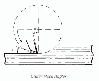
Cutter geometry
|
The angles for cutters used on MDF should be selected to achieve a balance between tool life and machined edge quality. A large cutting angle is required to ensure clean cutting with minimum wear of the cutting tip. A large clearance angle prevents the back of the cutter from rubbing against the machined edges. Increases in both these angles are however limited by the need to maintain an adequate thickness of metal at the tip. |
|
|
Feed speed
In order to machine edges requiring minimum sanding and filling, the feed speed should be selected to produce 8-10 cutter marks or scallops per cm compared with 6-8 marks per cm which would be acceptable in a typical wood machining operation. Recommended feed speeds which depend upon the number of cutters and the rotational speed of the block, can be calculated as follows:
|
|
RPM x No. of cutting edges |
|
Feed speed (m/min) = |
-------------------------------- |
|
|
100 x cutter marks/cm |
At lower feed speeds, the cutters will compress and abrade the MDF edges. The resulting high pressure on the tips and the increased temperature due to frictional heating will reduce the life of the cutters between sharpenings. At higher speeds, the greater spacing between cutter marks will increase surface roughness necessitating greater sanding effort to achieve the required level of smoothness before finishing.
Designs requiring heavy stock removal or intricate profiling may require a preliminary rough cutting or hogging operation followed by a second cut to achieve a smooth surface.
|
No. of |
Feed speed (m/min) |
||
|
|
3000 rpm |
4500 rpm |
6000 rpm |
|
3 |
11 |
17 |
22 |
|
4 |
15 |
23 |
30 |
|
6 |
22 |
34 |
43 |
Resharpening
Cutters should be resharpened at appropriate intervals in order to ensure clean cut edges free from burnishing or fibre tear. Cutting and clearance angles should be maintained at each sharpening to prolong the life of the cutters. Cutters should be ground on the face only to minimise a reduction in cutting diameter. Carbide tipped tools should be rough ground with a 100 diamond grit wheel and then polished with a 400-600 wheel to increase cutter life by improving chip removal and reducing resin build up.
The time for resharpening can be estimated approximately by periodic examination of the cut edges. A more positive method requires the measurement of electric current to the drive motor. Assuming that the operating current with a new tool fitted is 100%, resharpening can be scheduled when the current increases by a predetermined amount, usually in the range 110 to 120%.